http://www.facebook.com/profile.php?id=1738290019

My Facebook profile

WELCOME TO MY BLOG

Here you'll find some info on Ducati repair and modifications along with photos. I've got stuff for sale too, so check out the older posts. Please leave comments about anything you see, good or bad. Thanks for looking, Steve

Search This Blog

Friday, December 13, 2013

Carbon fiber work that I had on my website

CARBON FIBER


I’m attempting to duplicate some Ducati parts in carbon fiber. I’ve decided to work with fairly simple shaped parts until I perfect the technique or give up- (hardly unlikely, given my personality).

After doing hours of  internet researching and asking anyone with any knowledge of fiberglass, carbon fiber and vacuum bagging techniques, I decided to jump in.

The supplies: West Systems Vacuum Bagging Kit.

West Systems Resin System, 6 0z Fiberglass cloth and Loose Strand Fiberglass, CF cloth, also various throw-away brushes, foam brushes, mixing sticks/cups. 


Here's the instructions for the West Systems bagging kit. Click on the photos to enlarge them.

The West System Resin and Hardener comes in different temps- the 205 is a fast and the 207 is a slower hardener, but more importantly is a high gloss finish that is able to be clearcoated. The importance of this will be explained later.
Various shop supplies and equipment.


The kit comes with a vacuum generator (the black unit in the lower right of the picture) - this creates a vacuum from the air supplied from a air compressor. I've got a good size air compressor that would run for approximately 30 seconds every 5 minutes or so to create the pressure needed to make this happen. Note also, that the compressor and vacuum generator has to be on during the complete resin curing time...something the consider if the parts are curing overnight and the compressor is noisy-and, or- in the house.
Below: West System vacuum generator with working inlet pressures.

Note: I eventually bought a cheap Harbor Freight vacuum pump, to replace the vacuum generator.

Included in the kit is Peel Sheet, Breather cloth, Bag material, mastic tape and instructions. You'll also need Mold Release Wax, PVA, Fiberglass cloth/ resin, and of course Carbon Fiber cloth.

Below is the first pieces I attempted, they are aluminum heel guards from my Ducati ST2- it’s a simple shape with very little curves and positive draft angles, making it an easy part to duplicate with a mold.

After smoothing out the rough areas of the part (it was really beat up, cracked and scratched- but I’m not experimenting with new parts) and cleaning thoroughly I mounted them to a thick piece of tempered glass. I then decided I had to seal the open areas under the parts to stop the fiberglass from getting sucked underneath and making it difficult to remove. I also wanted to have a nice positive draft angle for a “flange” around the perimeter (so much for a simple part)—This took way too much time, but I was never able to find a better way to get around it.

Below 
I sealed the area with modeling clay.


The PVA is brushed on the part and around the area of the glass where the fiberglass will go. 

Above is the first attempt with the pieces on glass and no sealed areas (flanges).
Above: Here the parts and glass is shown in a envelope made from the bag material and mastic tape. The circles and "X"'s show where the vacuum suction cups will go. This is just for demonstration purposes only as the peel sheet and breather cloth will be over the parts once the fiberglass is applied and the vacuum process begins.

Below: I’ve sealed the edges and mounted the parts on a nice flat piece of artist’s board (MDF) Note the sealed edges done with modeling clay. The parts then get 10 coats of Mold Release Wax.


And then a coat or two of PVA as a final release agent.


Now here is an optional step that I learned about when I found a local expert who offered it up to me to try. It’s called a surface coat and it is used to coat the plug before the fiberglass is laid up. It forms a hard shell (it’s a two part epoxy coating) that will stay on the outer surface of the female mold (hopefully) giving the mold a nice hard, smooth surface with no “print-through”.

It gets carefully brushed on the surface of the plug, sets up in 2 to 4 hours and then can be covered with the resin and fiberglass.
Once the fiberglass has cured in the vacuum bag the mold can be carefully seperated from the plug bringing the Pro-Set coating with it. The wax and PVA should prevent the parts from sticking together.
The female mold. The surface should be hard and smooth, it can be carefully wet sanded to finish if it isn't, but I found this will most likely eat through the finish....it's best to work on the plug and try again.

Once I'm satisfied with the mold I prepare the surfacein the same way as the plug. First waxing it, then applying the PVA- No Pro-Set coating, of course. Lay the first layer of CF cloth in the mold making sure to leave enough around the perimeter to cover the flange area (this will be trimmed back later). Cover it with the release fabric and then the breather fabric, put it in a bag and slowly bring the vacuum up making sure the bag gets sucked down into the mold without too many creases or seams, you may have to release the vacuum and smooth it back down. Just do one layer now to make sure it conforms to the mold.
Below: a few layers of CF have been done and cured and I'm preparing the next layer.
After the first two layers, multiple layers can be done at once until the required thickeness and stength is obtained. I usually remove it from the mold after a couple of layer, check it's apperance and strength, then continue adding layers. The heel guards ended up being five layers.

OK, now a discussing about CF cloth- the pieces above and below are made from 2X2 twill weave in 3K weight (or tow). The 2X2 means the tow (groups of filaments- in this case 3,000 per tow) run over tow others than under two to make the pattern. It gives a look of a twill material and is IMHO the best looking pattern.

Click on the pic to see a larger image.

This is also a bilateral cloth which means the fibers run in both directions (vertical, horizontal), so there's no need to lay the cloth crisscross to obtain strength in multiple directions---BUT that get's into anotherdiscussion all together that is above my pay grade!!

The other type of cloth that I've begun to play with (there's many, actually) is Plain Weave.
Above: TOP- 2X2 Twill, BELOW- Plain Weave. Both in 3K weight.
Ducati and many aftermarket manufactures of carbon parts tend to use the plain weave for most parts. The twill, although looking really nice, can be a bear to work with on parts with a lot of curves and angles (like I discovered during my attempts at a full clutch cover). First it is very loosely woven which makes handling and cutting a delicate operation, just putting a slight pressure with a finger will distort the fibers and create "holes" in the weave! Then when attempting to "wet in" a piece, especially around a corner, it "smushes" out and ends up wavey. On realatively flat pieces like the heel guards it's not much of a problem, but I just couldn't get it right on the clutch cover which is basically a bowl with a lip at the top that has precision bolt hole locations!!!
So, after studying an aftermarket CF cover I had and realizing that it was made with Plain weave, that's what I ordered for the cover.

Alright, enough of that stuff---back to the heel guards.

Once the piece has been laminated with enough CF and has cured in the vacuum it's time to trim and polish (optional step) the part.

Here it is ready for trimming. Notice the resin "void" in the tip? This can happen if the vacuum bag does not conform tightly enough during the cure. I ended upmaking another part.

Now a very important disclaimer: Many of the steps above are my "attempts" at perfecting parts without the proper knowledge to do it the right way, hence the lousy quality of the finished product! I'll explain more as I go forward.

My next adventure was to attempt making a Ducati dry clutch cover. After a few crappy pieces pulled from lousy molds I decided to bug the hell out of my local expert. And what I came away with was the fact that I absolutely had to build the perfect mold before I even attempted to pull a part from it. When I say perfect I mean perfectly flawless, glossy and hard with no flaws what so ever!! This is what has been keeping me busy for the last two months and has just about done me in.
So let the frustration begin........

First you need a perfectly flawless, flat surface to mount the original part on. He told me I had to make one out of built up layers of fiberglass cloth, this also should have a small wall attached to the perimeter.

Following are pictures of my attempts at making the mold.
I will have to continue this page on another link as I've reached the limit allowed for posting pictures.


All the pictures above are from my attempt at a mold for the Ducati clutch cover. After many hours of work, I thought I had built the perfect mold only to discover holes in it while polishing. I also found more holes after filling them, sanding and polishing again. 
The holes are from air bubbles trapped between the gelcoat (Pro-Set) and the fiberglass used to form theshape of the mold. I had trouble getting the "chopped strand" fiberglass to form tightly around the cover especially at the radii of the flange. (I didn't vacuum bag this step, probably should have!!) Also when I poured the gelcoat over the cover it ran off and the surface had a very thin coat, so when the air got trapped between the gelcoat and fiberglass it weakened and broke through while buffing!!
This is the most frustrating part of this work---I reallythought I had made every mistake in the book, only to find out---at the end---I had made another!!
So right now, I'm left with a nice shiny mold with holes all over it. I haven't decided if I'm going to attempt to fill them with more gelcoat and sand and polish again, or just give up.....................

Monday, October 21, 2013

Friday, August 9, 2013

Custom arm for dial indicator

This arm is made from 1/8" brass rod. It sits around the top of the closing shim and facilitates the checking of the valve movement when doing cam timing.

Ducati Monster 8mm valve with MBP collet installed


Wednesday, August 7, 2013

Closing shim fully seated

Here's how the closing shim should look when the half rings are fully seated. Note how the top of the shim is flush with the top of the valve stem.
Note: 4V engines only.

Sunday, June 30, 2013

Carbon Fiber Work

Here's a ambitious project I attempted a while back, but have decided to put on the back burner for now. It is very time consuming and difficult to master, but I'll get back into it someday, probably when I retire from my "real" job!!

Sorry for the link--please copy and paste-
https://sites.google.com/site/tricklidzsm/carbon-fiber

Friday, June 28, 2013

CAMS AND CAM TIMING

Found a good article on this stuff--
http://www.compcams.com/Pages/416/valve-timing-tutorial.aspx

Wednesday, June 19, 2013

Bodywork repair-round 4

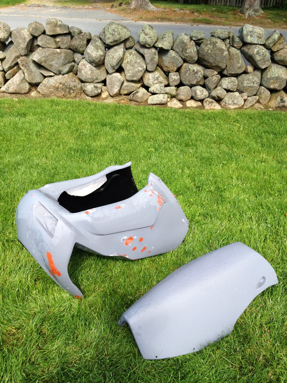
After my high side in the rain last year I had to retire the flat gray bodywork as seen above, because the tank was so severely dented on top from my shoulder!! (Got a nice deformed right shoulder now too... Oh well)

 I bought a used red tank and multi colored bodywork but only the tank was up to my standards, so I decided to put some old rashed ArmourBodies stuff I had from another crash. It needed a lot of work as the crash had left some pretty major through holes, mostly on the left side. 
 Above: The upper fairing after sanding and filling with fiberglass from the inside. I left the front snorkel areas painted as they are a pain to sand, they were not damaged anyway.
 Above: Decided to try something a little different with the Dzus fasteners on the upper fairing at the stay. I never really liked the clips on the fasteners on the top of the fairing, they don't seem to blend well with the aerodynamics of the fairing/windshield. When I saw that KurveyGirl (google it for nice parts) sold these fasteners without the clips (4mm Allen head) I decided to use them and recess them down into the bodywork!!

I did this by first drilling the hole through the fairing a little larger than the outside diameter of the head of the Dzus pin, then I layered up small sheets of Fiberglass mat, Kevlar cloth and Carbon Fiber to make up the thickness of the pin. Next I drilled through the exact center of the larger hole through the new pieces for the pin. Now the fairing is reinforced with cf and Kevlar at the mounting points (I also reinforced all the other mounting locations of the bodywork as well as where impact zones are- like the location of the underbody sliders, with Kevlar!)


Test fitting with windshield in place. Most of the sanding has been done.

I sprayed a couple coats of rattle can primer and filled the low spots with body filler and red putty. Below:


I then wet sanding with 240 grit paper bringing the filler down to the surface, and sprayed another couple coats of primer.
When I was relatively happy with the results, I sprayed more primer in the bare spots then wet sand with 600 grit.
I've decided to leave the bodywork primed for my first track day and paint it red when I have more time and my makeshift paint booth set up.
 Note the recessed areas for the air scoops where I masked off the red painted parts, this area is a pain the sand and because it had no damage I decided not to repaint it.

I've used it this way during the track day and it worked out well, doesn't look that bad, and came through the day with little damage. Actually, may race/track riders prefer to just use primed bodywork for ease of repair and cost. Any areas can be just hit with a little primer for a spray can. But, I don't know how long I'll keep it like this because I'm to finicky about looks!!

Sunday, March 24, 2013

Monday, March 4, 2013

BREMBO MASTER CYLINDER INFO

Some random information on Brembo clutch and brake master cylinders. The sheet above contains some notes I made while researching which Brembo masters I should use. I originally started with a 19X18 clutch and 19x20 brake.
I quickly realized the clutch master gave too heavy a pull so I got a 16X18 which along with a larger diameter slave cylinder resulted in a low effort pull of the lever. This combo makes it almost effortless disengaging the clutch. Highly recommended!
The 19X20 brake is also the ideal setup. Easy enough effort, good modulation and moderate lever travel. The only reason I went with the RCS 19 this year is because I wiped out the nonadjustable one in a crash. The RCS can be changed from a 19X18 to a 19X20 by removing the small rubber plug in the forward facing position on the lever (which is folding) and turning a small screw. I haven't experimented yet with the two options but will report here when I have.


 Above: Disassembled Brembo 19X20 brake master cylinder. Bore= 19mm (off slightly because I was moving the calipers to get picture)
 (Above)  Lever pivot to piston center= 20mm
 (Above) RCS19- Bore 19mm, lever pivot to piston center 18mm position 1
 Red marking on piston actuator rod will show red when in correct location.
Lever to piston center = 20mm, position 2
 Adjusting screw is below rubber cap in lever.
 Original 19X18 clutch master. Very stiff pull.
Perfect 16X18 master. the 16 mm bores are the perfect setups for clutches on the Ducatis.