http://www.facebook.com/profile.php?id=1738290019

My Facebook profile

WELCOME TO MY BLOG

Here you'll find some info on Ducati repair and modifications along with photos. I've got stuff for sale too, so check out the older posts. Please leave comments about anything you see, good or bad. Thanks for looking, Steve

Search This Blog

Monday, January 25, 2010

The laser worked well on the rear...

I decided to set it up to see if I could actually check the rake and trail numbers. Above you can see the laser set up to check the vertical line through the center of the axle to the ground. You can barely see the red line in the picture. I've got a T square set up to check the "plumb" of the line.
Close up of the vertical line.
I previously set the laser to follow along the centerline of the forks then moved it back to the centerline of the steering head, I confirmed the position by measuring back 27mm (the offset of the clamps) at the axle point. Then I marked the point where it hit the ground (actually a board under the tire to make up for the height of the stand) this is where the rake angle is.
To get the trail number I measured the distance between the two points marked on the board. And to my surprise I got 99mm, which is exactly what was quoted in the geometry figures I have, and what I calculated it would be working with the 27mm clamps.
So, overall, I'm happy I took the time to play around with the laser...Hey, it's no Computrack system, but it was nice to see how the geometry works when making changes. AND I like playing around with this stuff....Yeah, I know, I got way too much time on my hands!!!

A little experiment......

I decided to come up with a way to check the swingarm angle using a laser level that I had, but never used. I set the laser on a tripod, leveled it, then set the laser at the center of the swingarm pivot hole. Since I don't have the swingarm yet, because I'm waiting for a used 05 boxed arm, I set up a piece of plywood to follow the line back from the pivot point. I found it interesting that the swingarm pivot is in direct line with the crankshaft center. Follow the red line in the pic above.


The laser level worked surprisingly well.
While I had the front end apart I made some adjustments to the fairing stay so that the dash sat higher and angled back more, leaving more room for the throttle cables to run underneath.
It's easy to get front ride height measurements with the wheel off and the suspension fully suspended.

I ran a tie across the axle hole to locate the center and measured up to the top of the top triple clamp. For now I'm using some ride height figures that are suppose to work well with the clamps set at the steep (23.5 degree) setting. I set the forks to one line showing or 714mm to the axle center.

GETTING IT BACK TOGETHER......

The DucShop 27mm off set clamps are mounted up. I originally set the forks at three lines showing above the clamps because this is where they were with the stock clamps.


I ran a wire tie through the holes in the stem nut to mount the Starlane GPS unit. It plugs into the wiring harness and brings up lap times on the dash.

Tuesday, January 19, 2010

GEOMETRY.....

Now that I'm finished with the engine work, it's time to work on getting the "R" to handle like my sweet flicking 748! Since the cast swingarm of the 03 model is scratched (other side in this pic) from a previous get off, and I'll be looking to increase the wheelbase (more on that later, or see my older 27mm triple clamp post), I decided to find a nice 05 "boxed" swingarm to replace it.
While I had it off the bike, I took an accurate center to center reading to determine it's length. It's 483mm to the point where I had my chain adjusted (about the middle of the adjustment point) and 489mm all the way to the back of the adjustment range. I've been told that the 05 arm is about 513mm to the back, so I'll be able to get in the 500mm range with that arm, which is what I need. Stay tuned.
Above is an example of shoddy craftsmanship on a $30K (originally) motorcycle. All the tape on the wiring is cheap friction type that comes apart much too easily when trying to clean the harnesses. Plus, the wires are not completely taped, just wrapped with gaps!!! My other Ducatis were much better in this regard. I'll be fixing this problem with proper tape and technique, for sure!

One more thing on belt tension.....

Make sure that you check the tension of both belts at TDC compression for each one. Although the manual says nothing about bringing the Vertical cyl. back to TDC to set tension- (I've asked a couple of people about this and got a couple of different answers)- I decided, after getting a different reading by checking both belts with just the H.cyl @ TDC, to tension the V. belt at TDC also. I figured if it's good enough for the older superbikes it'll work here! New belts.
I had a small oil leak on the left (chain) side Vert. head rocker shaft cover. Above are the 5
O-rings that seal the oil in around the rocker shafts. My leak seemed to be coming from the upper right (orange) ring.
Here's the new one's greased up (so they stay in place) and installed.
All buttoned up. There's just enough room to get the cover off with the engine in the frame. The coolant elbow has to be removed first (there's an O ring in there too).
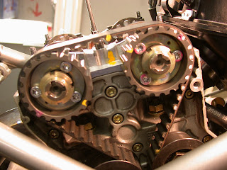
Another shot of all the marks that end up being on the cam wheels...it's good to know what's going on in the future....a Sharpie marker is your friend!!!

Cam Timing cont.

After making timing adjustments I marked the cam wheels for future reference. Note above-Intake @ 108 and Exhaust@ 107 and arrows showing which way the "cam" was turned. Notice the black line on the wheel of the intake side. This was in line with the notch on the nut before adjusting and now it is moved CW slightly. I made these marks as examples of what's taking place with the position of the parts involved before and after cam timing adjustments.
This pic above shows the position of the cam lobes when the piston is at TDC on the compression stroke. This is the cam position used for checking the belt tension.
Since I don't have the mechanical tensioning tool (I guess it's no longer in production) I decided to try my own "harmonic tensioning" system. Above- Korg tuner.

The manual states to "tune" the belts to 110Hz or an "A".....well, after a lot of trial and error I was able to get both belts tensioned to 110Hz. I then checked their tension the "old" way by twisting the belt between the rollers to see if it twisted 45 degrees and the "between the cam wheels" push test to get about 4mm flex! Both these tests proved that the tuning method worked out. Would I take the time to "harmonic" tension them next time?....maybe, we'll see. Note: I included the chart with the notes and Hz above to show the tight reading of 140Hz that should be used when checking cam timing.
The tuner and a rubber coated rod that I tried to use to tap the belts, but I found that just flicking them with my finger worked best. Another note: make sure it's really quite in the shop or you'll never get a true reading. AND have the tuner's mic postioned down near the layshaft pulley where the shop manual shows the Matheis tester being used.

Saturday, January 16, 2010

Cam Timing DONE!

Got 'em set to 107-107.
Well the Hor. Exh. ended up at 108.5...but that's close enough!!

VERTICAL CYLINDER

CAbove: My custom pointer set up on the exhaust closer.

I found that a adjustable spanner wrench fits into the holes in the closing cams and can be used to hold the cams while loosening and tightening the cam wheel bolts. I also used it to rotate the cams while making adjustments. Also note the T30 torque bit on the ratchet for the cam wheel attachment bolts. The feeler gauge takes up the slack of the opening clearance.Above-TDC gauge.
Above-
Degree wheel and pointer.

Well, it worked fine once I made some modifications to the end.

Friday, January 15, 2010

I'm CRAZY.........

and sick of trying to get the pointer of the dial indicator to sit nicely on the top of the closing shim....so, I made this thing. Hope it works...won't know until tomorrow!!!


VERTICAL CYLINDER CAM TIMING

I've made other marks (white) on the V cam wheels to show where they are in relationship to the top of the cylinder when the piston is at TDC on the compression stroke.
BTW- this position is about 270 degrees of crankshaft rotation from the point where the H cyl. was at TDC. Also take note of the "T" slots in the end of the camshafts, this is also a good refernce for cam position (about 12 o'clock)
Here's the layshaft position, note the yellow mark (TDC on H cyl). I later made a white dot on the wheel at the crankcase reference line, so WHITE for "V" cyl, YELLOW for "H" cyl. (paint sticks are nice for this)


Remember that the belts have to be really tight with almost no tension in them to check the cam timing as the slack will throw the readings off. If you're using the Harmonic Tensioning technique I was told they should be tightened to about 140 Hz. I've played around with this technique and will post more info here later, but for now, I just put them really tight.

This picture shows the homemade tool I use the find piston TDC. I've used it for years with all my Ducatis and it works well. The dial gauge sits on the top.


Horizontal Cylinder cam timing check.

I made a spreadsheet to keep track of my readings. You can see by the numbers on the bottom (Horizontal Cylinder) that the exh. cam was right on, but I had to advance the intake cam 4 degrees (2 degrees at the camshaft) to get 107.
The degree of crankshaft rotation is checked at 1mm. of lift or .040" on the dial gauge.


It's tricky, but possible, to get the pointer right on the top of the closing shim. After much experimenting and talking to others who have attempted this, I've found that it's best to rotate the crank forward (CCW) until the valve opens to .040". Record the reading on the degree wheel as valve opens. Then back it up (against rotation- CW) until the needle goes back to "0" (TDC on the degree wheel). Continue against rotation until the cam goes all the way around and then moves the needle on the dial gauge back to .040". This is the point where the valve is 1mm. before fully closed. Record this on the sheet as "valve closes".
A couple of notes: 1. Make sure the needle stops right at "O" when coming back from the "valve opens" point! If it's off a little--something moved or it jump slightly on the shim---start over!!
2. I found it's best when backing the crankshaft up (CW) to go past the "valve close" point a few degrees then come back to it with a correct engine rotation.


This shows a reading of 17 degrees ATDC on the degree wheel. (H. exh. closing)


Monday, January 11, 2010

Here's the cheap cam wheel holding tool I got from Ebay. It does work to hold the cam wheels from turning while installing the belts.

Had to run out the other night to find a 26mm offset box wrench. All Sears had was this massive straight job that didn't fit (BTW- it's used to adjust the belt tensioner roller)....so after a little work on the bench grinder....


The dial gauge with it's pointer extension.
Testastretta means "narrow head", and though it makes checking and adjusting the valves a lot easier than the older "4 valvers", it's a lot tighter getting the pointer in position for cam timing!!


I used the radiator support pin on the frame to clamp the flexible arm of the dial indicator to. This tool is made to check brake drum runout on cars and trucks, but has served me well (price is right too) for this type of work.
Another thing I did after trying to see into the Horizontal head while sitting on the work stand was to raise the front of the bike up a couple of feet and add two more 2X6 supports. This was I don't have to bend over as far and it stops all the oil that constantly runs out of the head onto the oil cooler.


I had to fab a custom bent rod for the dial indicator. It took a lot of trial and error to get it right, the trick is to have the end sit on the top of the closer shim and follow the shim through the complete movement of the valve without hitting the cam of popping off the shim!!! Next to the rod is a picture of the neat Ducati tool shown in the repair manual....it would be nice to have one of these....but I can just image the price!!


Above the degree wheel set at TDC Compression, Horizontal Cylinder.
(Right) fuzzy pic of the rod sitting on the Intake opener Right side.


Above and Right: Cam timing worksheet that I made to keep track of everything. I also compared the readings the Brad Black's MotoOne worksheet!