
DUCATI 4 VALVE NOTEBOOK
Various techniques and tips for Ducati engines.

DUCATI 748 NOTEBOOK
- INCLUDED: CHECKING SQUISH, OIL FEED HOLE, VALVE CLEARANCE AND ADJUSTMENT
DON'T BE AFRAID TO DIVE IN!!

SETTING SQUISH
1MM Solder is positioned in the squish area of the combustion chamber with Play Dough.

Special wax in varying thicknesses can also be used on the piston crown.

Wax can also be used in the combustion chamber. WD40 should be applied to the piston crown to prevent sticking to the wax.


- Adjustment is made with base and head gaskets to obtain 1mm of clearance (squish) when head bolts are properly torqued. I used Cometic gaskets- they can make them in any thickness.
Note lines in chamber where head gasket sits. Squish area is just inside gasket in flat area before the chamber tapers down toward the valves.

After applying wax or solder, assemble head with gasket and torque to specs, then turn engine over by hand past TDC. Disassemble everything and check the thickness of the wax or solder.
Measurements can be taken with a micrometer or vernier calipers.
 (above- measuring "squished" solder with micrometer)
 Don't forget to use the proper sealant on final assembly!!


Deck height can then be modified with a combination of head and base gaskets until the desired 1mm squish is set.
CLEANING PISTONS AND CHECK RING END GAP.
Thoroughly clean the piston crowns of carbon build up. Use soft blade (a kitchen pairing knife works well) in valve cutouts and 3M pad and soft wire wheel on crown.


Piston componets.

Fit each ring in the bore and check the end gap
 Note end gap marked with arrows above. Check specs in manual.
OIL FEED HOLE REPAIR
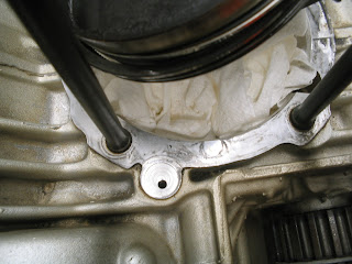

Here a 4mm set screw is inserted into the oil feed hole in the Vertical cylinder crankcase. Use red loctite. This eliminates a potential oil leak at the base gasket. I filled the recessed area with 1411 Three Bond sealant and eliminated the green O ring. (area in red above)

OIL FEED HOLE REPAIR


My 1998 748 didn’t have an oil feed hole in the front (Horizontal) cylinder crankcase. I understand some models may have one. (see picture below)
These passages are for air cooled models that don’t have external oil lines like the SBK’s.

ROCKER ARMS
- Top rocker is stock, bottom is a reconditioned one.


VALVE ADJUSTMENT

Work bench set up with wood supports for the heads.

I've got a thing about having a neat, comfortable, well-lit area to work in. It makes life so much easier!!

A little trick (below) to keep the opening rocker arms out of the way while working on the shims...

Note the piece of solder wrapped around the top of the head and under the rocker arm.


Feeler gauge set up---again, a little extra work and planning makes it easier.
Make sure everything is organized.


Valves are “lapped” back in. NOTE: This work was done after having new valve guides and regrinding the valve seats.
Here’s my universal, closer shim tool and digital micrometer.
The 1mm feeler gauge that closes off the back side of the shim is mounted to a small block of wood, this makes it easier to use with one hand.


Here a screwdriver with a protective rubber sleeve over the shaft holds the closing rocker arm against the helper spring and away from the shim.

Make sure to write down all the clearances and sizes of the shims. This chart shows the shims needed.
Here a burr is removed from a shim that was difficult to remove from the valve stem.
A few thousands of an inch can be carefully removed from a shim by rubbing them in a circular motion on sandpaper and a piece of glass. I start with 220 grit, then follow by 400 and 600 sandpaper and a little WD40 for lubrication. Be sure to check the progress as you go....there's no going back!!!


Make sure the closing shim is properly seated: Note that the top of the valve stem and top of the shim are flush. You may have to "snap" the rocker arm against the bottom of the shim a couple of times to make it seat. I flick the screwdriver tool holding the rocker arm against the holder spring a couple of times.
Install the cams and opening rockers and check the opening and closing clearances.
BELT TENSION----ALTERNATE PROCEDURE!!


When I first started messing around with these "beasts" I became confused about the proper way to tension the belts. I'd read all the info and had all the "experts" on various forums tell me the proper (and only--according to them) way to set the tension. I had used the "twist the belt to 45 degrees method" in the Haynes manual and it seemed to work OK--if not a little unreliable. AND I was not about to cough up the big bucks for the super-duper Ducati tensioning tool!!
So I decided to do what I've always done when in doubt----ask the Guru---Bruce Meyers, formerly of BCM fame and now semi-retired. He shot back his usual--"Don't worry about it, just set it to about 4mm play between the top pulleys with finger tension!" When I asked which finger I should use, he just laughed and said, matter-of-factly...."You're pinky" and hungup.
Now, Bruce wouldn't be happy if I didn't take that advice on step farther--(he knows me pretty well)..and I came up with the rig above. Again, making something complicated out of something easy is my claim to fame!
I think from the pictures you'll get the idea...
Works well to when checked against the other methods!
RANDOM, BUT USEFUL CAM TIMING INFO


Above: A Cam Timing worksheet I made to help keep track of what's happening....


OFF SET WOODRUFF KEY
I had to advance the V Intake cam eight degrees of crankshaft rotation.
This Ducati off set key marked with 4 dots moves the pulley either way (advance or retard) 4 degrees on the camshaft.
Because the camshafts spin at 1\2 crankshaft speed this 4 degree adjustment equals 8 degrees at the crankshaft.
Make sure to use a new nut.


I used a large, curved jaw ViseGrip pliers along with an old belt to hold the pulley.
I used a 1\2” drive impact wrench to remove the nut.

Notice the red loctite on the threads. Make sure the pulley is fully seated. I tapped it with a plastic hammer and checked to see if the same amount of threads were showing once torqued down. I had this nut loosen on my Paso while traveling 80 mph, two-up---NOT FUN!!!


Enjoy,
Steve
Hey, leave a comment......
Comments
Mcx Tips
I really appreciate your post and you explain each and every point very well.Thanks for sharing this information.And I'll love to read your next post too.Regards:- http://www.mcxbhavishya.com/
mcx tips - Oct 9, 2011
No comments:
Post a Comment